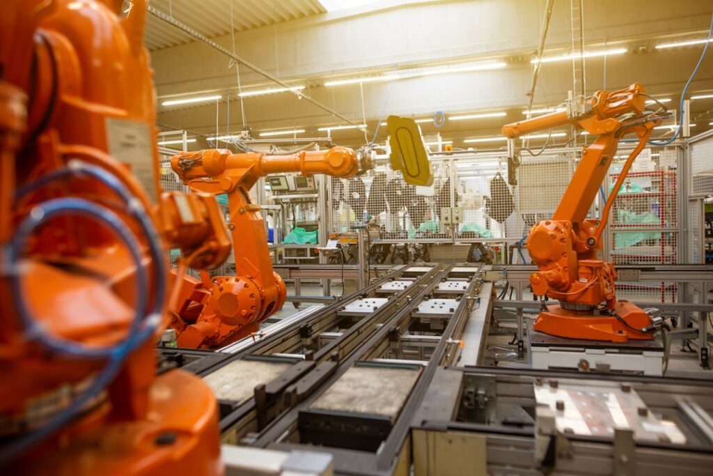
A linear bearing is the component that converts rotary input from a ball screw, belt, or actuator into repeatable, low-friction translation along a precision shaft. Unlike a rotary bearing that supports radial or axial loads on a spinning member, a linear motion bearing is engineered to carry loads while guiding a carriage, table, or end effector in a straight line. Whether you are sizing automation for a packaging line, upgrading a CNC router, or designing medical dispensing equipment, the right linear bearing directly influences positioning accuracy, system stiffness, and total cost of ownership.
At BearingRate, our complete Linear bearing catalog covers metric and inch dimension types, standard and extended-length models, and integral flange options for simplified mounting. In this guide, we explain how a linear ball bearing works, compare common form factors such as the linear bushing and flange linear bearing, and provide a practical linear bearing selection guide and industrial linear bearing maintenance strategy you can apply immediately.
What Is a Linear Bearing and How Does It Work?
A linear bearing is a rolling or sliding element assembly that rides on a hardened shaft or rail and constrains motion to one degree of freedom. The most common industrial design is the recirculating linear ball bearing. Inside the outer sleeve, ball circuits are loaded against the shaft; as the carriage moves, balls roll along the shaft raceway, enter a return channel, and recirculate continuously. This mechanism converts sliding friction to rolling friction, allowing smooth motion with starting coefficients of friction typically below 0.005.
Key benefits of a recirculating linear bearing include:
- Low friction and high mechanical efficiency
- High load capacity relative to envelope size
- Precise repeatability when paired with ground shafts
- Interchangeable outer dimensions across many metric and inch standards
- Minimal stick-slip, supporting high-speed indexing and positioning
When the application requires the bearing to be pressed into a housing, a plain cylindrical linear bushing is used. When a mounting flange is needed for axial location or cantilevered loads, a flange linear bearing integrates the flange into the outer sleeve, eliminating the need for a separate retaining ring or end plate.
Common Linear Bearing Types and Application Fit
Industrial automation uses several standardized product families. Selecting among them starts with shaft dimension system, load envelope, and mounting geometry. Below are the most widely specified ranges available from BearingRate.
LM type linear bearings are the compact metric standard used throughout Asian and general-purpose automation equipment. Their small outer-diameter-to-bore ratio makes them ideal for space-constrained slides, pick-and-place gantries, and semiconductor handling modules. Browse the LM type range for standard and extended-length options.
LME type linear bearings follow the European metric standard, offering slightly different outer dimensions and ball circuits from the LM type. Equipment built to DIN-style specifications or retrofitted from European OEM slides often specifies LME units to maintain original clearances and housing fits.
LMB type linear bearings are the inch-dimension counterpart commonly found in North American machinery, robotics, and factory-automation builds. If your design uses fractional-inch shafting or you are replacing components in legacy equipment, the LMB type range provides direct dimensional compatibility.
ST type linear bearings are support-rail assemblies that combine a precision shaft, support blocks, and recirculating ball bushings into a ready-to-mount system. These are well suited for long-span gantries, door mechanisms, and material handling conveyors where shaft support and rigidity are critical.
Load, Accuracy, and Life Considerations
Sizing a linear bearing correctly requires more than matching bore diameter. Engineers should evaluate dynamic load rating C, static load rating C0, moment capacity, and expected travel life. The basic rating life L10 for recirculating ball linear bearings can be estimated using the relationship L10 = (C / F)3 × 50 km, where F is the equivalent dynamic load. For oscillating or shock-loaded applications, reduce the calculated life by an application factor that accounts for vibration, contamination, and misalignment.
Accuracy is determined by shaft quality, housing bore tolerance, and internal clearance. Ground and hardened shafts in the 58–64 HRC range with surface finishes below 0.4 µm Ra will deliver the lowest friction and longest life. Preloaded or clearance-adjustable variants can remove backlash in precision positioning axes, but they increase drag and require tighter geometric tolerances.
Moment loads must be addressed through bearing spacing, twin-bushing arrangements, or selecting a flange linear bearing that resists overturning forces. When in doubt, distribute the load across two bearings spaced as far apart as the design allows; this reduces individual bearing reaction forces and improves system rigidity.
Sealing, Lubrication, and Industrial Linear Bearing Maintenance
Industrial environments expose linear motion components to dust, metal chips, washdown chemicals, and temperature swings. Proper sealing and lubrication are therefore not optional; they are central to life expectancy. Most steel-recirculation units ship with synthetic grease and polymer or metal shields that retain lubricant while excluding particulates.
A practical industrial linear bearing maintenance plan should include:
- Visual inspection of seals and shafts during scheduled machine downtime
- Relubrication at intervals based on duty cycle, speed, and contamination level; high-speed or dirty environments need shorter intervals
- Shaft cleaning with lint-free wipes and compatible solvent before applying fresh grease
- Monitoring for scoring, brinelling, corrosion, or excessive noise, which indicate contamination ingress or fatigue
- Verification that retaining rings, flange bolts, and housing fits remain tight after thermal cycling and vibration
- Documenting replacement dates and batch numbers to support predictive maintenance programs
Using the correct lubricant grade is essential. General-purpose lithium soap greases work for many factory floors, while food-grade, high-temperature, or vacuum-compatible greases are required for specialized sectors. Never mix incompatible greases without cleaning the assembly; thickener incompatibility can cause separation and premature failure.
Installation Best Practices for Linear Bushings and Flange Units
Even a correctly selected linear bearing can underperform if installed incorrectly. Because the outer sleeve is thin-walled and the balls run directly against the shaft, small errors in housing bore or shaft alignment multiply into vibration, binding, and short life.
Start by machining housings to the recommended H7 or J7 tolerance depending on whether a clearance or transition fit is desired. Press the linear bushing squarely into the housing using a mandrel that contacts the outer ring only; never press through the ball circuit. For flange linear bearing units, seat the flange against a machined shoulder and tighten mounting screws in a star pattern to avoid cocking the sleeve.
Shaft alignment is critical in multi-bearing arrangements. Use one fixed support and one floating support, or ensure that parallel shafts are within 0.02 mm over the full travel length. Excessive misalignment loads the ball tracks unevenly, causing early pitting and noisy operation. After installation, run the carriage by hand through the full stroke; any tight spots or roughness indicate alignment or contamination issues that must be corrected before commissioning.
A Practical Linear Bearing Selection Guide
A disciplined selection process prevents over-specifying expensive components or underspecifying for reliability. Use the following steps as your linear bearing selection guide:
1. Define the load case. Calculate radial forces, moment loads, and any impact factors during acceleration and deceleration.
2. Choose the motion profile. Determine maximum speed, acceleration, stroke length, and cycle frequency; high-speed applications may need ball-recirculation designs with optimized return paths.
3. Match the dimension standard. Decide between metric LM or LME types and inch LMB types based on existing shafts, housings, or regional supply chains.
4. Select the form factor. Use a standard linear bushing for simple press-fit housings, a flange linear bearing for through-panel or cantilevered mounting, and an ST type assembly for long-span shaft support.
5. Specify accuracy and preload. Pick standard, precision, or high-precision grades to match positioning tolerance and budget; add preload only when backlash must be eliminated.
6. Account for the environment. Specify seals, corrosion-resistant materials, special lubricants, and protective covers for contaminated, wet, or clean-room conditions.
7. Plan maintenance access. Ensure shafts, lubrication fittings, and retaining hardware can be reached safely during normal service intervals.
By documenting these decisions early, procurement teams can source consistently across assemblies, and design engineers can avoid costly redesigns when production volumes increase.
The right linear bearing is a small component with an outsized impact on machine performance. From compact LM type and inch LMB type units to ready-to-mount ST type assemblies, matching the bearing family to the load, accuracy, and environmental demands of your application will improve reliability and reduce total cost of ownership. Combine careful sizing with disciplined industrial linear bearing maintenance and precise installation, and your linear motion bearing systems will deliver the repeatable, low-friction performance that modern automation requires.